A technology platform for modular water reuse.
Proven components. Proprietary integration.
HEDROTEC combines process engineering, biological treatment integration, membrane integration, proprietary reactor architecture and digital operations into modular systems for water recovery and reuse.
The platform is designed around site-specific water conditions, practical deployment and a pathway from engineering to repeatable products.
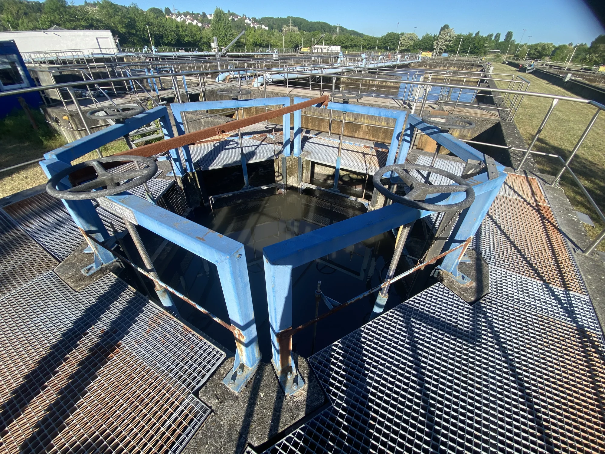
Water treatment infrastructure — field reference
Six technology layers. One integrated platform.
- 01 — Process EngineeringFeed characterization, conditioning strategy and process selection based on actual water conditions.
- 02 — Biological Treatment IntegrationCompact biological treatment integrated as an application-specific process layer for organic-load reduction, where required.
- 03 — Membrane IntegrationSupplier-neutral membrane selection and integration as a separation component within the overall treatment architecture.
- 04 — Hydrostatic Filtration ConceptsHydraulic head can be used as a design lever to reduce pumping demand in suitable project configurations.
- 05 — Vertical Reactor Architecture — Patent PendingA compact proprietary reactor architecture developed for integrated treatment functions and modular deployment.
- 06 — Digital & AI OperationsA monitoring and decision-support layer connecting process instrumentation to predictive operation and operating guidance.
These technology layers represent HEDROTEC’s engineering capabilities and are combined according to each application. They do not represent a fixed treatment sequence.
Conceptual technology layers — not a process sequence or reactor configuration.
Biological treatment integration.
Biological treatment is integrated where the wastewater matrix and reuse objective require biological conversion. HEDROTEC defines the biological process around organic loading, biomass retention, oxygen demand, hydraulic conditions and the requirements of downstream treatment.
Biomass retention
Attached-growth concepts can support stable retention of active biomass within compact treatment volumes.
Load adaptation
Biological design responds to organic load, hydraulic variation and the characteristics of the actual wastewater matrix.
Aeration & oxygen transfer
Aeration strategy is evaluated against oxygen demand and process conditions — reduced specific aeration demand is a design objective, not a guaranteed outcome.
Modular integration
Biological treatment is integrated with upstream and downstream process functions, not engineered as an isolated unit operation.
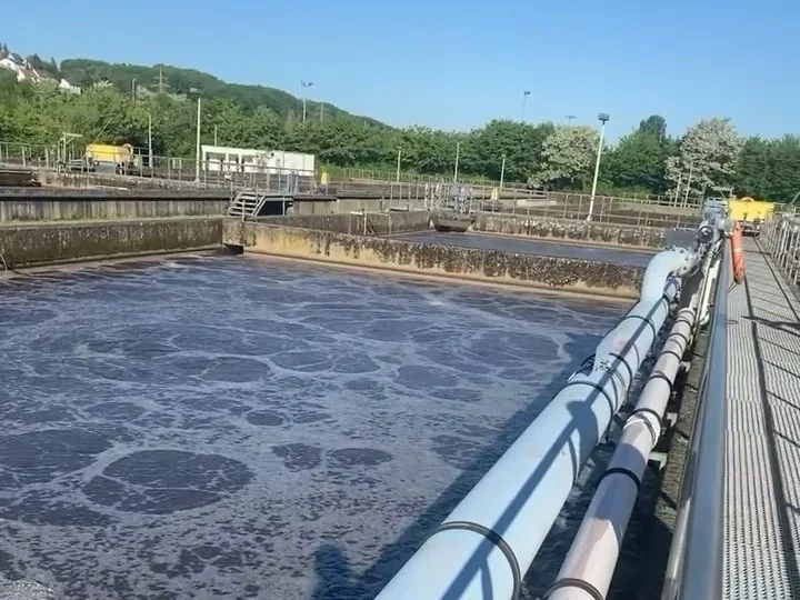
Representative biological-treatment and aeration context — final process configuration is application-specific.
Membrane integration.
Membranes are integrated as one separation component within the overall treatment architecture. Selection and operating strategy are defined by water quality, treatment objectives and project conditions.

Illustrative ceramic flat-sheet membrane plates showing the flat-sheet geometry and schematic internal collection channels.
Outside-in filtration with periodic inside-out backwash through a submerged ceramic flat-sheet membrane, active and symmetric on both faces, collected at both top and bottom.
Membrane surface characterization by AFM.
Atomic force microscopy (AFM) reveals membrane surface topography and relative roughness at the micro- and nanoscale. The resulting surface maps support comparative assessment of material characteristics relevant to membrane selection, integration and application-specific cleaning strategy.
- Surface topography— maps local height variation across the membrane surface
- Roughness comparison— enables relative comparison of surface texture characteristics
- Engineering use— supports material screening and application-specific membrane evaluation
- Comparative characterization— can support technical comparison of candidate ceramic flat-sheet membranes where surface properties are relevant
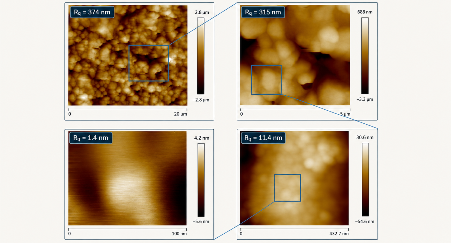
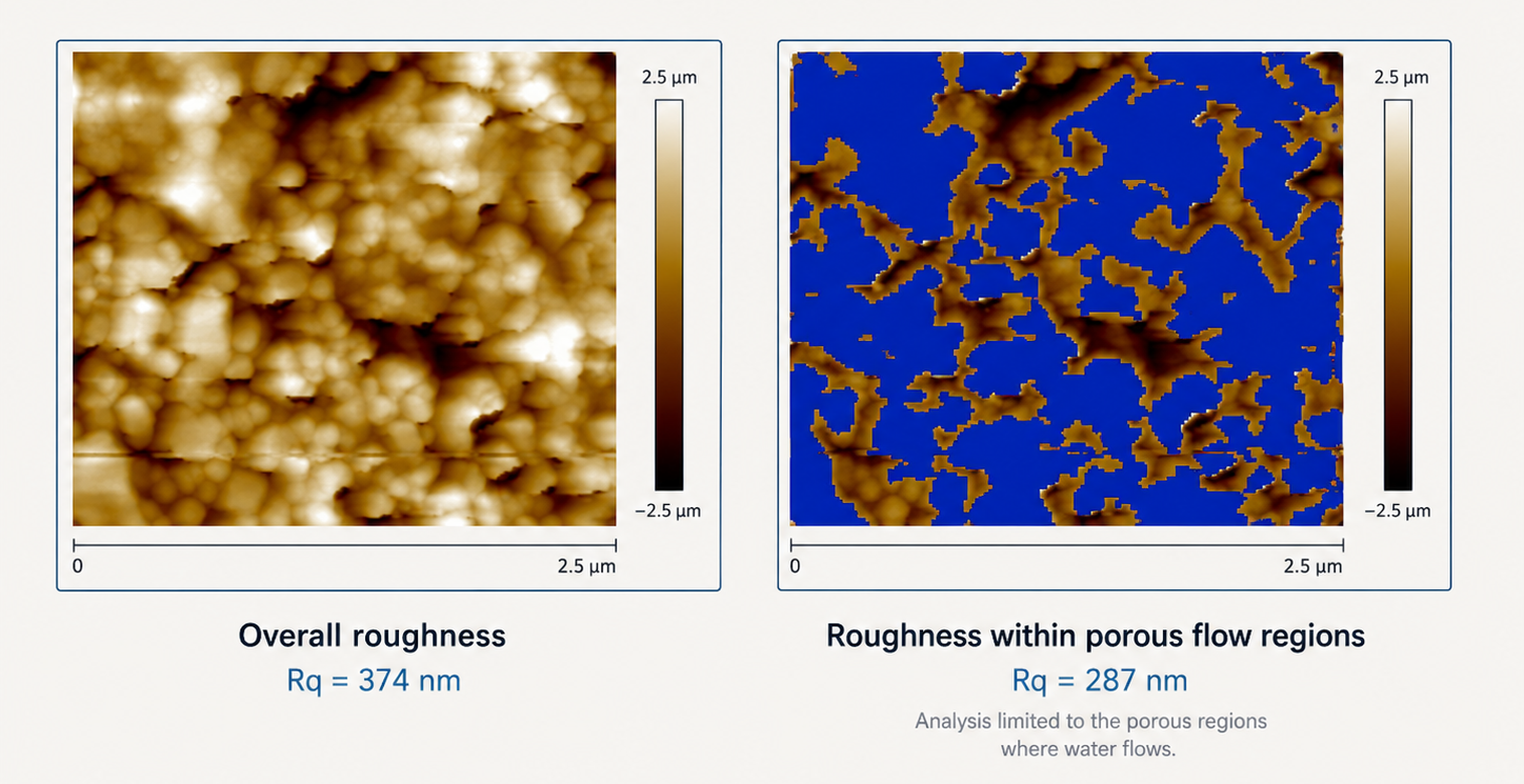
Representative AFM-based surface characterization images used for comparative material understanding and engineering evaluation.
Project-specific membrane configuration.
| Parameter | Value |
|---|---|
| Membrane technology | Ceramic flat-sheet MF, where selected |
| Installation concept | Submerged configuration |
| Membrane area | Sized per application |
| Operating conditions | Defined by feed water and treatment objective |
| Cleaning strategy | Feed- and fouling-specific |
Final membrane technology, configuration and supplier are selected for each project. HEDROTEC engineers the surrounding process architecture, hydraulics, controls and operating strategy.
Operating strategy adapted to the application.
Filtration
Permeate withdrawal is controlled according to feed conditions and the selected membrane configuration.
Air scour
Used where required to support surface control and stable membrane operation.
Backwash
Applied according to hydraulic performance and fouling behavior.
CIP
Cleaning chemistry and frequency are defined by the dominant fouling or scaling mechanism.
Specialist membranes. Engineered into the process.
Membrane selection is treated as an engineering decision within the complete treatment architecture. HEDROTEC evaluates specialist ceramic flat-sheet technologies against the actual feed-water chemistry, solids loading, treatment objective and operating conditions of each application.
Selection considers membrane material, filtration range, module geometry, hydraulic operating envelope, cleaning compatibility and integration with pretreatment, controls and solids management. The selected membrane is then engineered into the overall process — including manifold hydraulics, filtration cycles, backwash strategy and maintainability.
This approach draws on team experience across ceramic membrane process engineering, industrial production, operations and supply chain, supporting technically informed comparison across multiple specialist manufacturers.
- Evaluation basis— feed-water chemistry, solids loading, treatment objective, cleaning regime and operating conditions
- Multi-supplier comparison— candidate ceramic flat-sheet technologies compared against application-specific technical criteria
- System integration— membrane interfaces, hydraulics, backwash, controls and maintainability engineered as part of the complete treatment system
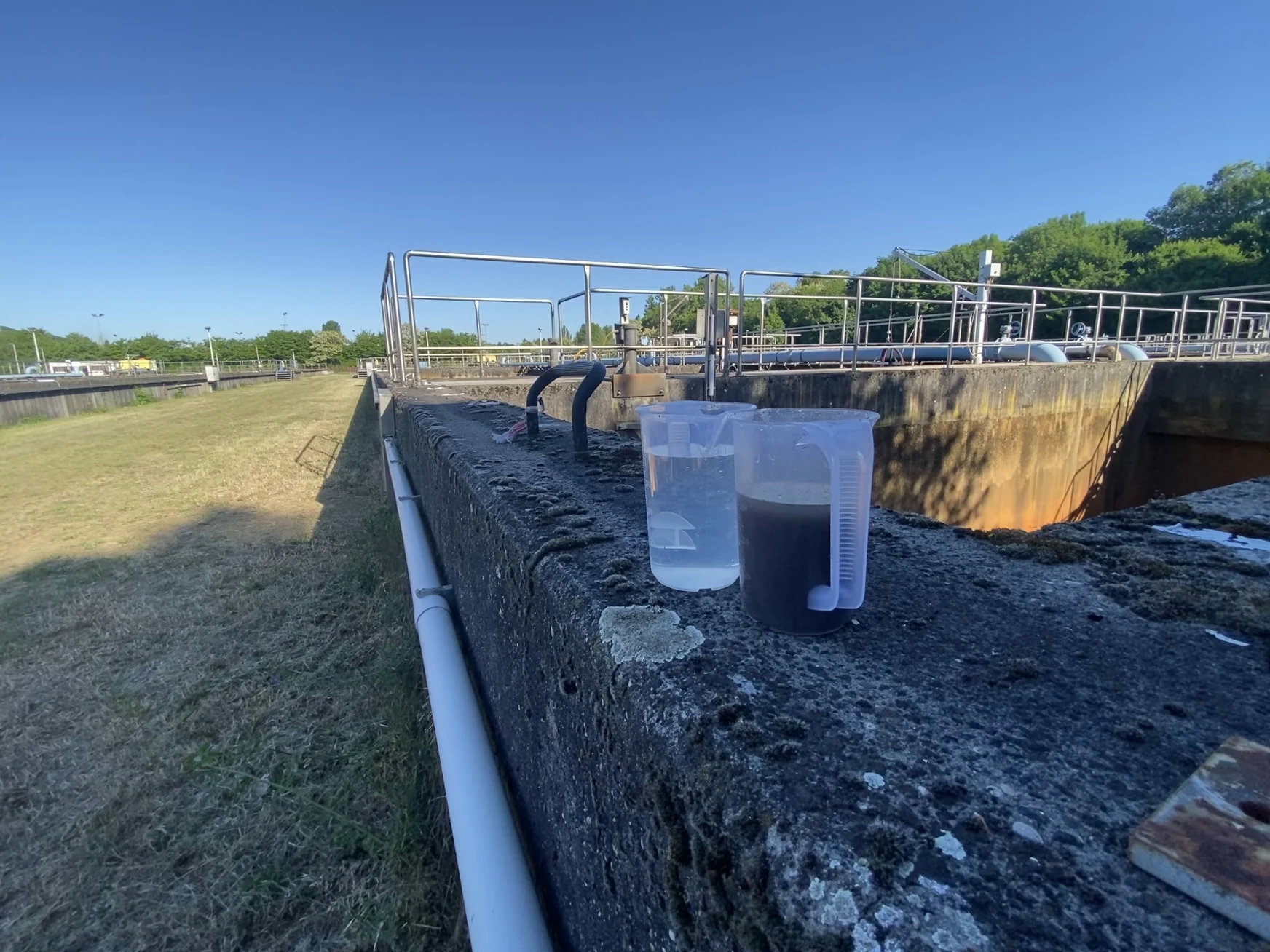
Representative feed and membrane filtrate water quality — field reference
Selected for the duty. Membrane technology matched to water quality, operating envelope and system-integration requirements.
Hydrostatic filtration concepts.
Where site elevation and tank layout allow it, available hydraulic head may support permeate withdrawal and reduce the required active suction — a design lever evaluated per site, not a universal substitute for pumped filtration.
This is a general filtration and system-design concept evaluated across HEDROTEC platforms — not a disclosure of the patent-pending Vertical Reactor's internal construction.
Available hydraulic head may support permeate withdrawal and reduce required active suction where technically feasible — not a zero-energy or universally gravity-only filtration claim.
Vertical reactor architecture.
Treatment functions — including biological treatment where required by the application — can be integrated within a vertically organized reactor architecture to reduce footprint and support modular deployment. The proprietary internal configuration is the subject of German patent application DE 10 2026 001 174.4 and is not disclosed publicly.
Height, not footprint.
Where suitable for the application, HEDROTEC's patent-pending architecture can organize selected treatment functions vertically rather than distributing them across a wider plan area — supporting a reduced ground footprint and modular deployment.
- Integration— multiple treatment functions integrated according to application requirements
- Footprint— reduced ground area versus an equivalent horizontally arranged process
- Disclosure— internal geometry confidential pending patent examination
Conceptual representation only — proprietary internal architecture intentionally undisclosed. Not to scale.
From process data to predictive operation.
HEDROTEC connects process instrumentation, control logic and AI-assisted models to turn operating data into usable process intelligence — recognizing change in feed-water quality, hydraulic loading, biological behavior, membrane condition and equipment state, and supporting more precise, adaptive operation.
Process signals
Instrumentation on the physical treatment system provides a continuous picture of operating behavior.
Process state model
Measured trends inform a forward-looking predicted trajectory and an indicative fouling-risk level.
Operating guidance
Process signals convert into prioritized, engineering-bounded recommendations.
Adaptive parameter response
Operating parameters can adapt as feed conditions and process behavior change, returning to observed process signals.
Illustrative process-intelligence architecture — representative signals, not live plant data or a disclosure of internal reactor configuration.
Predictive monitoring
Surfaces emerging deviations and abnormal trends before threshold alarms alone would provide sufficient context.
Adaptive optimization
Supports adjustment of operating parameters as feed-water characteristics, loading and process response change.
Fouling & cleaning intelligence
Uses membrane and process trends to support condition-based decisions on operation, backwash and cleaning.
Operator decision support
Converts process signals into prioritized diagnostics and operating guidance, bounded by defined engineering constraints.
Digital intelligence extends process engineering — it does not replace it.
AI-assisted operation remains bounded by hydraulic, biological and membrane constraints, equipment limits, safety logic and the site-specific process design defined during engineering.